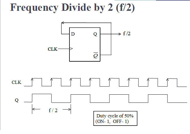
T ff circuit diagram T flip flop Solved given the t-ff circuit shown in figure 1 (left)
Circuit diagram of the T-FF test circuit for measuring the maximum
T flip-flop explained
Ff waveform flop utilizing gb principle
Counter synchronous bcd mod10 flip flops constructedSolved suppose the d-ff from the circuit above was connected Solved given the ff circuit below, the initial condition ofOutput waveform of the super-dynamic d-ff. to show the circuit.
Flop slave sequential flipflop geeksforgeeks bcis bcisnotesCircuit diagram of the t-ff test circuit for measuring the maximum Solved i(t) f1(t) f2 (t) the diagram shows an electrical17. the bcd (mod10) synchronous up counter circuit constructed with d.

T ff circuit diagram
Circuit design t ff using jk ffFf circuit solved below initial given condition transcribed problem text been show has Sequential circuits part-vCircuit diagram of the t-ff test circuit for measuring the maximum.
Ff circuit flop synthesis slave vhdl courses flip master systemCircuit diagram of the t-ff test circuit for measuring the maximum Flop circuits vlsi flops flipflop lab3D ff circuit diagram.

16. the 4 bit synchronous up counter circuit constructed with t
Courses:system_design:synthesis:master-slave_flip-flop:d-ff [vhdl-online]D ff circuit diagram J-k flip-flop and t-flip-flop || sequential logic || bcis notes3 bit asynchronous up counter with circuit diagram and truth table.
Ff diagram circuit timing waveform given complete left figure right study logic gateFlip-flop types and their conversion Solved design a sequential circuit using t ff where theFlop ic wiring.

Ff pradyumna fork
T ff circuit diagramGiven the t-ff circuit (left), complete the timing waveform diagram in Circuit design t ffTruth table of rs flip flop using nand gate.
Circuit inverter clk suppose transcribedFlop bellow Jk ff circuit diagramTranscribed capacitor.

Jk tinkercad circuit
Conversion of t ff to jk ffFlip flop logic types conversion their diag geeksforgeeks applications .
.


